
Digital Logic Gates :Digital electrical circuits operate on two logic levels: logic low and logic high. The voltage range corresponding to Logic Low is denoted by ‘0’. Similarly, the voltage range corresponding to Logic High is denoted as ‘1’.
A logic gate is a basic digital electrical circuit with one or more inputs and a single output. As a result, logic gates form the foundation of any digital system. These logic gates may be divided into three types.
- Basic gates
- Universal gates
- Special gates
Let us now go over the logic gates that fall into each category one by one.
Basic Gates
NOT Gate
The NOT gate has a single input and a single output, with the output always being the inversion (i.e. negation) of the input. This indicates that if the input is 0 and the output is 1, and vice versa.

The NOT gate is an electrical circuit that outputs an inverted version of the input. It is sometimes referred to as an inverter. The inverted output is known as NOT A if the input variable is A. This is alternatively represented as A’, or A with a bar across the top, as seen at the outputs. The illustrations below illustrate two methods to construct the NAND logic gate to form a NOT gate. The same thing may be done using NOR logic gates.
| A | Y = A’ |
| 0 | 1 |
| 1 | 0 |
AND Gate
The AND gate may accept numerous inputs but only has a single output. Only if all of the inputs are high will the output be high; otherwise, the output will be low.

The following table shows the truth table of 2-input AND gate.
| A | B | Y = A.B |
|---|---|---|
| 0 | 0 | 0 |
| 0 | 1 | 0 |
| 1 | 0 | 0 |
| 1 | 1 | 1 |
OR Gate
OR gates are multi-input, single-output gates that have their output equal to logic ‘zero’ when all of their inputs are low. Furthermore, for every conceivable remaining combination of inputs in which at least one of the inputs is high, the output is logically high.

In this case, A and B are the inputs, while Y is the output of a two-input OR gate. If both inputs are ‘0,’ then the result, Y, is also ‘0.’ The outcome, Y, is ‘1’ for the remaining input combinations.
The symbol of an OR gate is shown below, with two inputs A and B and one output, Y.
Alternatively, Gate
This OR gate outputs Y, which is the logical OR of two inputs A and B. Similarly, if ‘n’ inputs are present, the OR gate gives an output that is the logical OR of all those inputs. That is, an OR gate’s output will be ‘1’ if at least one of its inputs is a ‘1’.
truth table of 2-input OR gate.
| A | B | Y = A + B |
|---|---|---|
| 0 | 0 | 0 |
| 0 | 1 | 1 |
| 1 | 0 | 1 |
| 1 | 1 | 1 |
Universal gates
NAND and NOR gates are referred to as universal gates. Because we may build any Boolean function in sum of products form using only NAND gates. Similarly, we may build any Boolean function in product of sums form using only NOR gates.
When an AND gate is combined with a NOT gate, it produces a NAND gate, which is a multi-in, single-out logic gate. This gate’s output is only low if all of its inputs are logically high. In contrast, the gate’s output will be high for any other input combination.
NAND gate
The NAND gate is the result of combining the AND and NOT gates. This gate produces the same outcome as a NOT-AND operation. This gate can accept two or more input values and output just one value.

In this case, A and B are the inputs, while Y is the output of a two-input NAND gate. When both inputs are ‘1,’ the result is ‘0.’ If at least one of the inputs is a zero, the result, Y, is a ‘1’. This is the inverse of two input AND gate operation.
The graphic below depicts the symbol of a NAND gate, which has two inputs A and B and one output, Y.
The following table shows the truth table of 2-input NAND gate.
| A | B | Y = A.BA.B’ |
|---|---|---|
| 0 | 0 | 1 |
| 0 | 1 | 1 |
| 1 | 0 | 1 |
| 1 | 1 | 0 |
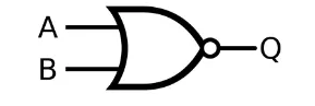
What is NOR Gate?
A NOR gate is a digital logic gate that implements logical NOR; it acts as shown in the truth table below. If both inputs to the gate are LOW (0), a HIGH output (1) is produced; if one or both inputs are HIGH (1), a LOW output (0) is produced.
The negation of the OR operator yields NOR. It is also, in some ways, the inverse of an AND gate. NOR is a fully functional operation—NOR gates can be combined to produce any other logical function. This trait is shared by the NAND gate. The OR operator, on the other hand, is monotonic since it can only turn LOW to HIGH and not vice versa.
Only when all of the inputs are low will the NOR gate’s output be high. Simply put, this gate returns the OR gate’s complement result.
The NOR gate’s logical or Boolean expression is the complement of logical multiplication of inputs, indicated by the plus sign as
(A+B)’=Y
When all of its inputs are set to 0, the value of Y is true.
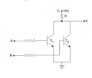
Circuit Diagram of NOR Gate
Digital Logic NOR Gate Types
Based on the input it accepts, the NOR gate is also categorised into three categories. The following are examples of NOR gates:
The NOR gate with two inputs

It is a basic version of the NOR gate, much like the other gates. There are just two input values and one output value in this sort of NOR gate. There are 22=4 potential input combinations. The following is the truth table and logic design:
Because the term “NOR gate” implies “not an OR gate,” the output of this logic gate is the inverse of that of an OR gate.
We know that an OR gate’s output is 0 only when all of its inputs are 0. As a result, in the instance of the NOR gate, the output is only 1 when all of the inputs are 0. In all other circumstances, that is, for all other input-output combinations, the outcome is 0.
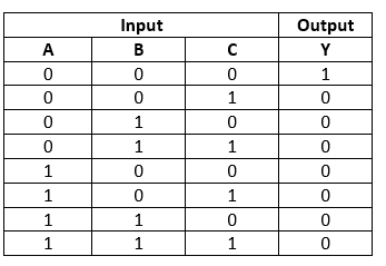
Truth tables list the result of a certain digital logic circuit for all conceivable input combinations. A two-input NOR gate’s truth table is expressed as follows:
| A | B | Y= (A+B)’ |
| 0 | 0 | 1 |
| 0 | 1 | 0 |
| 1 | 0 | 0 |
| 1 | 1 | 0 |
The NOR gate with three inputs
The 3-input NOR gate, unlike the 2-input N gate, has three inputs. The logic NOR gate’s Boolean statement is defined as the binary action addition (+). The NOR gate can be cascaded to produce an infinite number of separate inputs. There are 23=8 potential input combinations. The following is the truth table and logic design:
Making an AND Gate from a NOR Gate
The NOR operation of a two-input NOR gate is as follows:

Now, D.Morgan’s theorem is that
Now, if we substitute inverted A for A and inverted B for B in the previous equation, we obtain
This is a combination operation.
Special gate
Special gates are Ex-OR and Ex-NOR gates. Because these two gates are subsets of the OR and NOR gates.
XOR Gate
The XOR gate is also known as the Ex-OR gate. The XOR gate is utilised in half and full adders and subtractors. The exclusive-OR gate is also known as the EX-OR or X-OR gate. This gate can have two or more input values and only one output value.

In this case, A and B are the inputs, while Y is the output of a two-input Ex-OR gate. For the first three rows, the truth table of the Ex-OR gate is the same as that of the OR gate. The only change is in the fourth row. That is, when both inputs are one, the output Y is zero rather than one, because the inputs have an even number of ones.
When just one of the two inputs is ‘1’, the output of the Ex-OR gate is ‘1’. When both inputs are the same, it is zero.
The symbol for an Ex-OR gate is shown below, with two inputs A, B and one output, Y.
| A | B | Y = A⊕B |
|---|---|---|
| 0 | 0 | 0 |
| 0 | 1 | 1 |
| 1 | 0 | 1 |
| 1 | 1 | 0 |
XNOR Gate
The XNOR gate is also known as the Ex-NOR gate. The XNOR gate is utilized in half and full adders and subtractors. The exclusive-NOR gate is also known as the EX-NOR or X-NOR gate. This gate can have two or more input values and only one output value.
The truth table of a 2-input Ex-NOR gate is shown in the table below.
| A | B | Y = A⊙B |
|---|---|---|
| 0 | 0 | 1 |
| 0 | 1 | 0 |
| 1 | 0 | 0 |
| 1 | 1 | 1 |
In this case, A and B are the inputs, while Y is the output. For the first three rows, the truth table of the Ex-NOR gate is identical to that of the NOR gate. The only change is in the fourth row. When both inputs are one, the result is one rather than zero.
When both inputs are the same, the output of the Ex-NOR gate is ‘1’. When both inputs are different, it is zero.
The symbol of an Ex-NOR gate is shown below, which has two inputs A, B and one output, Y.
Related posts