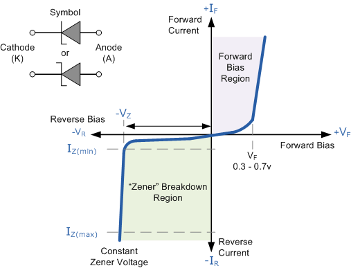
When current reaches the Zener voltage, a Zener diode not only permits current to flow from anode to cathode, but also in the opposite direction. Zener diodes are the most widely used semiconductor diodes because of their feature. Let’s learn about the functioning, construction, and more of Zener diodes in this article.
A Zener diode is a particular kind of diode made to consistently let current to flow “backwards” when a specific reverse voltage, called the Zener voltage, is attained.
There is a wide range of Zener voltages used in the fabrication of Zener diodes, some of which are even changeable. The reverse conduction in some Zener diodes happens as a result of electron quantum tunnelling in the small gap between the p and n regions; this phenomenon is known as the Zener effect, named after Clarence Zener, and occurs when the p-n junction is sharp, heavily doped, and has a low Zener voltage. Avalanche breakdown occurs during operation and has a more progressive junction in diodes with greater Zener voltages.
How Zener Diodes Controls Voltage Drop
The voltage drop across a forward-biased diode connected in series with a resistor and a DC voltage source will be reasonably consistent throughout a large range of power supply voltages, as shown in figure (a) below.
A forward-biased PN junction’s current flow is proportional to the forward voltage drop multiplied by e. Due to the exponential nature of this function, current increases rather quickly for even small increases in voltage drop.
Another way to think about this is to state that even for significant fluctuations in diode current, the voltage dropped across a forward-biased diode remains relatively constant. The voltage of the power supply, the series resistor, and the diode’s voltage drop—which, as we know, doesn’t fluctuate significantly from 0.7 volts—all work together to restrict the diode current in the circuit depicted
The voltage drop across the resistor would nearly double with an increase in power supply voltage, while the voltage across the diode would somewhat decrease. In contrast, a loss in power supply voltage would cause a nearly equal drop in resistor voltage and a marginal drop in diode voltage.
How does a reverse bias Zener Diode function?

When it is forward-biased, a Zener diode behaves just like a regular diode. However, when coupled in reverse biassed mode, a little leakage current passes through the diode. Current begins to flow through the diode when the reverse voltage rises to the specified breakdown voltage (Vz). The series resistor-determined maximum current is reached before the current stabilises and remains constant throughout a broad range of applied voltage.
A Zener diode can break down in one of two ways:
- Avalanche Breakdown
- Zener Breakdown
Avalanche Breakdown
At high reverse voltage, avalanche breakdown happens in Zener diodes and regular diodes. The PN junction receives a large amount of reverse voltage, which gives the liberated electrons enough energy to accelerate rapidly. High-velocity collisions between these free electrons and other atoms release additional electrons. The amount of free electrons produced as a result of this constant collision causes the electric current in the diode to rise quickly. The conventional diode could get irreversibly damaged by this abrupt surge in electric current. A Zener diode, on the other hand, is made to function under avalanche breakdown and can withstand the abrupt surge in current. Zener diodes that have a Zener voltage (Vz) greater than 6V experience avalanche breakdown.
Zener breakdown
Either impact ionisation, which occurs above 5.5 V, or the Zener breakdown effect, which occurs below 5.5 V, are to blame for the breakdown. Each mechanism has a different temperature coefficient, but they both produce the same behaviour and don’t need any special electronics.
The temperature coefficient of the impact effect is positive, whereas the temperature coefficient of the Zener effect is negative. The Zener diodes rated at roughly 5.5 V are the most stable over a wide variety of temperature conditions because the two temperature effects are almost equal at this voltage and cancel each other out.
The regulator for a zener diode
Under various load current settings, zener diodes can generate a stabilised voltage output with little ripple. The zener diode will conduct enough current to sustain a voltage drop of Vout if a modest current is passed through it from a voltage source via an appropriate current-limiting resistor (RS).
We recall from earlier lessons that the half-wave or full-wave rectifiers’ DC output voltage has ripple superimposed upon it, and that the average output voltage varies with the load value. By connecting a simple zener stabiliser circuit as shown below across the output of the rectifier, a more stable output voltage can be produced.
Specifications for zener diodes
Specifications for zener diodes can vary, including packaging, power dissipation, maximum reverse current, and nominal working voltage. Specifications that are frequently used include:
- Voltage Vz: The reverse breakdown voltage (-2.4 V to approximately 200 V; up to 1 kV; maximum for surface-mounted device (SMD) is roughly 47 V) is referred to as the Zener voltage.
- Maximum current at the specified Zener voltage Vz is -200 uA to 200 A.
- Minimum currents of -5 mA and 10 mA are necessary for the diode to fail.
- Voltage tolerance is often ±5%.
- Diodes around 5 V offer the best stability in terms of temperature.
- Leaded and surface-mount components can be packaged separately or inside integrated circuits.