
op amp as comparator :A comparator is a type of electrical circuit that compares two inputs and provides an output. The comparator’s output value shows whether one of the inputs is bigger or less. Please keep in mind that the comparator is one of the non-linear IC applications.
Because an op-amp has two input terminals, an op-amp-based comparator compares the two inputs that are applied to it and outputs the outcome of the comparison. This chapter goes on op-amp-based comparators.
The Basic Comparator
The voltage comparator is the only typical op-amp application that employs the device in its original high-gain, differential-input design. A voltage comparator’s aim is to provide an output signal that corresponds to the greater-than-or-less-than connection between the voltages at the input terminals of the op-amp.
If we consider the comparator’s output to be a digital signal, we can say that it generates a logic high when the voltage at the non-inverting input is greater than the voltage at the inverting input and a logic low when the voltage at the non-inverting input is less than the voltage at the inverting input.
Comparator Varieties
The Op-amp comparator compares one analogue voltage level to another, or to a predetermined reference voltage, VREF, and generates an output signal based on this voltage comparison. To put it another way, the op-amp voltage comparator compares the magnitudes of two voltage inputs and decides which is the greater of the two.
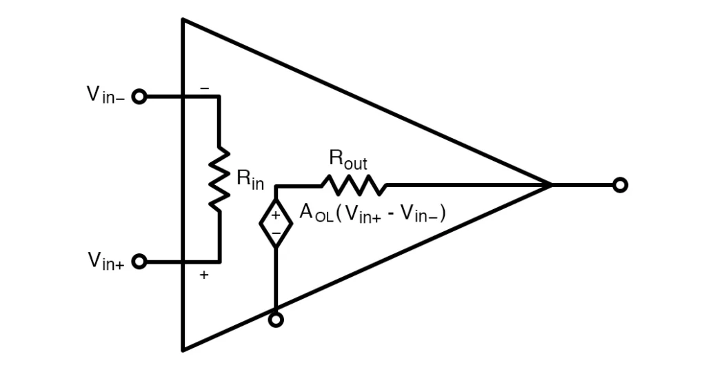
In earlier courses, we saw how the operational amplifier may be utilized with negative feedback to regulate the size of its output signal in the linear domain while executing a number of tasks. We’ve also seen that the conventional operational amplifier is distinguished by its open-loop gain AO and that its output voltage is provided by the expression: VOUT = AO(V+ – V-), where V+ and V- represent the voltages at the input and output, respectively.
There are two kinds of comparators: inverting and non-inverting. This section goes into depth regarding these two sorts.
Op amp as Inverting Comparator
An inverting comparator is an op-amp-based comparator that receives a reference voltage at its non-inverting terminal and an input voltage at its inverting terminal. This comparator is known as an inverting comparator because the input voltage to be compared is supplied to the op-inverting amp’s terminal.
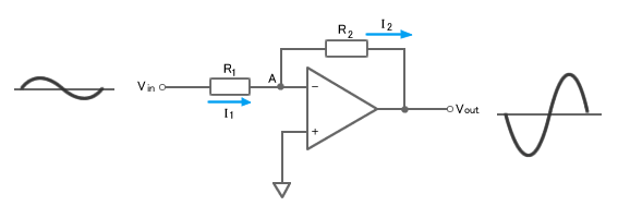
The circuit seen in Fig. 2 amplifies and inverts (reverses the phase of) the input signal before outputting the result. The circuit employs negative feedback, which involves inverting portion of the output signal and returning it to the input. Feedback occurs in this case because the output Vout is linked to the inverting input (through resistor R2).
Let’s take a closer look at how this circuit works. If the output is not connected to a power supply, the voltages applied to the inverting () and non-inverting (+) inputs are identical; the two inputs behave as if they are shorted together; we may imagine an imagined short. Point A will be at 0 V since the voltage differential between this imaginary short and the non-inverting input is 0 V. So, according to Ohm’s Law,
I1 = Vin/R1.
Op amp as Non Inverting Comparator
A non-inverting comparator is an op-amp-based comparator in which the input voltage is supplied to the inverting terminal and the reference voltage is applied to the non-inverting terminal. This op-amp-based comparator is known as a non-inverting comparator because the input voltage to be compared is applied to the op-non-inverting amp’s terminal.
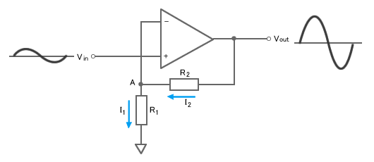
The non-inverting amp varies from the inverting amp in two significant ways: (1) the output waveform is in phase with the input waveform, and (2) the input is connected to the non-inverting input terminal (+). However, both non-inverting and inverting circuits employ negative feedback.
So, how does this circuit work? We still have the imaginary short, which implies that the non-inverting (+) and inverting () inputs are both at voltage Vin. So point A is also at Vin. Ohm’s Law states that the voltage at R1 equals Vin = R1 I1. And because there is basically no current flowing into either of the op-amp inputs, I1 = I2. And, because Vout is the sum of the voltages at R1 and R2, we know that Vout=R2 × I2 + R1 × I1. We can rearrange these expressions to find the gain G, like this: G = Vout/Vin = (1 + R2/R1)
Related posts