
A low pass filter is a filter that allows low-frequency signals to pass while blocking or obstructing high-frequency ones.
In other words, low-frequency signals flow through considerably easily and with less resistance, but high-frequency signals pass through much more difficultly, which is why it is a low pass filter.
Low pass filters can be made by combining resistors with capacitors or inductors. A low pass RC filter is a low pass filter made out of a resistor and a capacitor. A low pass RL filter is one that has a resistor and an inductor.
On this page, we will go through both of these types of circuits and demonstrate how RC and LC low pass filters are built. Both circuits contain the
What is a Low Pass Filter?
A low pass filter is a filter circuit that accepts just low pass frequency components and rejects all other higher frequency components. The word LPF stands for low range frequency.
Circuit for a Low Pass Filter
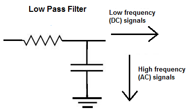
The circuit schematic for a low pass filter is illustrated below. It consists of two passive parts, a resistor and a capacitor, which are coupled in series with an applied input voltage across the resistor and an output voltage acquired across the capacitor.
First Order Low Pass Filter
A first-order filter, for example, reduces the signal amplitude by half (so power decreases by a factor of 4, or 6 dB) every time the frequency doubles (goes up one octave); more accurately, in the limit of high frequency, the power rolloff reaches 20 dB every decade.
A first-order filter’s magnitude Bode plot consists of a horizontal line below the cutoff frequency and a diagonal line above the cutoff frequency. At the boundary between the two, there is also a “knee curve” that seamlessly transitions between the two straight line zones. If a first-order low-pass filter’s transfer function has both a zero and a pole, the Bode plot flattens out again at some maximum attenuation of high frequencies.
There are two kinds of first order low pass filters. They have
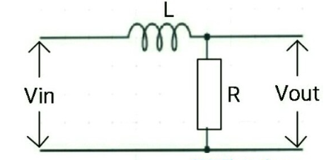
First Order Inductive Model Low Pass Filter
The impedance of the inductor increases as the frequency of the input increases.
As a result, the high frequency impulses are not transmitted to the load via the inductor.
Low frequency transmissions, on the other hand, pass through.
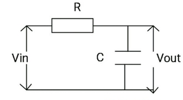
First Order Low Pass Filter Capacitive Model
The impedance of the capacitor reduces as the frequency of the input rises.
As a result, high frequency impulses pass through the capacitor, and the majority of the voltage is decreased over the load.
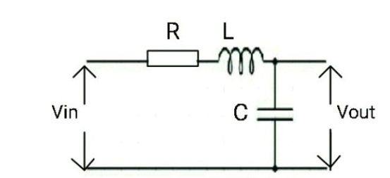
Second-Order Low Pass Filter
As illustrated in the picture below, the second-order low pass filter circuit is an RLC circuit. The output voltage is obtained by measuring the voltage across the capacitor. Because two passive components, an inductor and a capacitor, are employed to block the high frequencies of the input signal, this form of LPF operates more effectively than first-order LPF.
A second-order filter has a steeper attenuation of high frequencies. The Bode plot for this sort of filter is similar to that of a first-order filter, except it falls down faster. Every time the frequency doubles, a second-order Butterworth filter reduces the signal amplitude to one-fourth of its original level (so power decreases by 12 dB per octave, or 40 dB per decade).
This is a low pass RL filter circuit. It operates on the basis of inductive reactance. Inductive reactance describes how the impedance, or resistance, of an inductor varies in response to the frequency of the signal travelling through it.
Unlike a resistor, which is a nonreactive device, an inductor, like a capacitor, provides varying impedance values to signals of varying frequencies. Inductors, unlike capacitors, provide very high resistance to high-frequency impulses while providing low resistance to low-frequency signals.
Frequency of Cutoff
All low-pass filters have a fixed cutoff frequency. This is the frequency at which the output voltage is less than 70.7 percent of the input voltage. Although it may appear such at first appearance, the cutoff percentage of 70.7 is not arbitrary.
It is the frequency at which capacitive reactance in ohms equals resistance in ohms in a basic capacitive/resistive low-pass filter. The cutoff frequency of a basic capacitive low-pass filter (one resistor and one capacitor) is given as:
This is the frequency at which the magnitude of the transfer function equals 0.707, or 1/√2

Noise Currents in Differential Mode (DM) and Common Mode (CM)
- DM signal currents are out-of-phase currents that communicate intended data, whereas CM signal currents are in-phase and give no useful data. CM currents, while having a significantly smaller amplitude than DM currents, are the primary source of regulated radiated and conducted emissions testing difficulties.
- In an ideal world, DM signals go along one side of a circuit track, while an equal and opposite DM signal travels along the opposite side. To avoid DM to CM conversion, the PCB layout must be precise, with no circuit discontinuities. This guarantees that the DM signals are completely cancelled and that no CM current is generated.
Π Filter
The low-pass filter resembles the Greek letter. It consists of a capacitor from the line to be filtered to return, an in-circuit series element (resistor, inductor, or ferrite), and another capacitor from the line to be filtered to return.
T Filter
The T low-pass filter is shaped like the letter T. It has an in-circuit element (resistor, inductor, or ferrite) put on the filtered line, a capacitor inserted on the return line, and then another in-circuit element (resistor, inductor, or ferrite).
Applications
The following are examples of low pass filter applications.
- Used to eliminate noise from high-frequency communications.
- In audio applications.
- In biomedical applications
- Used in electronic applications like as loudspeakers, subwoofers, and so on.
- In digital-to-analog converters.
- Filters used to prevent analysis
- Wave analyzers, audio amplifiers, and equalizers all use it.
Conclusion
Low-pass filters are the most common type of filter utilised in EMC operations. There are various possible topologies to select from, based on several criteria such as the frequency of the intended signals, source and load impedances, and the presence of common or differential mode noise sources in the circuit.
Non-ideal behaviour of passive components, parasitic circuit elements, too much DC current present in ferrites circuits, utilising a filter with a low cut-off frequency, hence drastically attenuating desirable signals, and poor layout and placement are all factors that render low-pass filters useless.
Related posts