
What is a Current Divider?
A current divider is a linear circuit that generates an output current that is a fraction of the input current. This is accomplished by connecting two or more parallel circuit elements; the current in each branch will always split in such a manner that the overall energy used in a circuit is minimised.
Because of its capacity to proportionately split total current into fractional portions, a parallel circuit is also known as a current division.
To grasp what this implies, consider analyzing a basic parallel circuit and finding the branch currents via individual resistors.
Current division are parallel circuits that divide the source or supply current into several parallel channels. In a parallel linked circuit, all of the components’ terminals are connected together and share the same two end nodes. This creates several pathways and branches for the stream to flow or pass through. However, the currents might vary depending on the component.
Parallel circuits are distinguished by the fact that, while distinct currents flow through separate branches, the voltage is shared by all linked channels. That is, VR1 = VR2 = VR3… and so on. As a result, the necessity to determine individual resistor voltages is avoided, allowing branch currents to be determined using Kirchhoff’s Current Law (KCL) and, of course, Ohm’s Law.
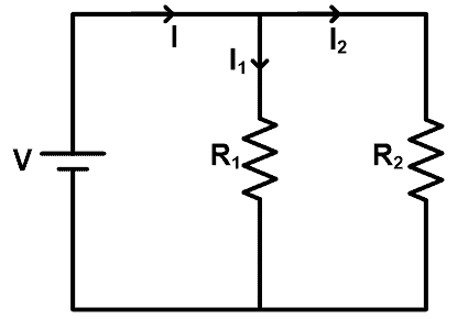
A DC source is used to power all resistors in this example. The voltage across resistors is the same as the voltage across the source. However, due to the parallel connection, the current splits into many routes. The current splits at each node, and the current value is determined by the resistance.
Using the current division rule, we can directly determine the value of current travelling through each resistor.
The principal current provided by the source in this case is I. It also splits into two resistors, R1 and R2. I1 is the current that flows through resistor R1, and I2 is the current that flows through resistor R2.
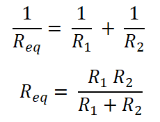
Because the resistors are linked in parallel. As a result, Req is the equal resistance.
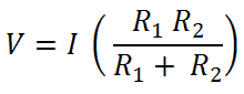
Now According to Ohms Law
V = I R
For Current I1 is
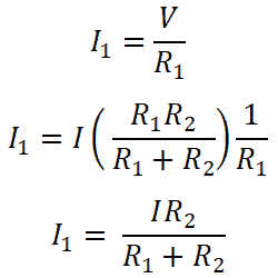
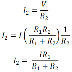
Similarly for current I2 is
Conductances are used in current division.
The conductance approach is another easy way to find the branch currents in a parallel circuit. Conductance is the reciprocal of resistance in DC circuits and is symbolised by the letter “G.” Because conductance (G) is the inverse of resistance (R), which is measured in Ohm’s (), the inverse of Ohm’s is known as “mho” (). (an inverted ohm sign). As a result, G = 1/R. The Siemen is the electrical unit for conductivity (symbol S).
As a result, for parallel-connected resistors, the equavalent or total conductance, CT, equals the sum of the individual conductances as indicated.
When Can You Apply the Current Divider Rule?
The current divider rule can be used in the following situations:
When two or more circuit elements are linked in parallel with the voltage or current source, the current divider rule is utilised.
When the overall circuit current and equivalent resistance are known, the current divider rule may be used to calculate individual branch currents.
When two resistors are linked in series, the current in any branch is a fraction of the total current (IT). If both resistors have the same value, the current will flow evenly through both branches.
What is a Voltage Divider?
A voltage divider is a basic circuit that converts a high voltage to a low value. We can generate an output voltage that is a fraction of the input value using simply two series resistors and an input voltage. Voltage division are among the most basic circuits in electronics.
If studying Ohm’s law is like learning the ABCs, knowing about voltage dividers is like learning how to spell cat.
Voltage division is the outcome of dividing the input voltage among the division’s components. Two resistors linked in series are a simple example of a voltage division, with the input voltage applied across the resistor pair and the output voltage arising from the connection between them.
How to Determine a Voltage Division Circuit’s Output ?
One of the most frequent and useful circuits used by engineers is the two resistor voltage divider. The major goal of this circuit is to reduce the input voltage to a lower amount based on the resistor ratio. Given the input (or source) voltage and resistor values, this calculator may help compute the output voltage of the divider circuit. Keep in mind that the output voltage in actual circuits may change due to resistor tolerance and load resistance (where the output voltage is linked).
Vout=Vin∗R2R1+R2Vout=Vin∗R2R1+R2
Where:
VoutVout = Output voltage. This is the scaled down voltage.
VinVin = Input voltage.
R1R1 and R2R2 = Resistor values. The ratio R2R1+R2R2R1+R2 determines the scale factor.
The current flowing through the series network is simply I = V/R following Ohm’s Law. Since the current is common to both resistors, (IR1 = IR2) we can calculate the voltage dropped across resistor, R2 in the above series circuit as being:

Likewise for resistor R1 as being:

Applications
Voltage dividers have several uses and are among the most frequent circuits used by electrical engineers. Voltage division can be found in a variety of places, including the following.
- Potentiometers
A potentiometer is a variable resistor that may be used to make a voltage divider that can be adjusted. - Resistive Sensors Reading
In the actual world, many sensors are simply resistive devices. A photocell is a variable resistor that generates resistance in proportion to the quantity of light it detects. Variable resistors include devices such as flex sensors, force-sensitive resistors, and thermistors. - Shifters of Levels Voltage dividers are also handy when a voltage has to be smoothed down. The most frequent example involves connecting signals with two distinct voltage levels between a sensor and a microcontroller. Most microcontrollers run at 5V, however certain sensors can only handle 3.3V. To avoid sensor damage, you should naturally level the voltage from the microprocessor.